10 USB Pinout Explained- USB A, B, C(Male and Female)
Last updated on April 5th, 2024 at 03:51 pm
Universal Serial Bus (USB) is an electronic device that gives us a universal medium for connecting peripherals. It can be a keyboard, printer, speaker, a storage device, or a mobile phone.
With time, USBs have evolved in type, functionality, and efficiency. So, it becomes important to select the best variant from the available types that perfectly suit our purpose. In this article, we will discuss the pinout of different USB ports or Connectors to get a better idea of their structure and connection.

Table of Contents
The USB pinout can be divided into two parts: USB Connector Pinout and USB port Pinout. The connector here refers to the device that goes into the USB port. For example, a wired Mouse is connected to the laptop by inserting its connector into the USB port.
Hence the terms Male version for Connector and Female version for the USB port are tossed.
USB type A and type B pinout(male and female)
USB Type-A is used to make a connection with a PC while Type B is used to connect smaller peripherals. In other words, Type A is a downstream connector, while Type B is an upstream connector.
The USB type A is rectangular, while type B has a square-like shape. Both of them have 4 pins. The figure below shows the Pinout of Male and Female versions of both USBs.
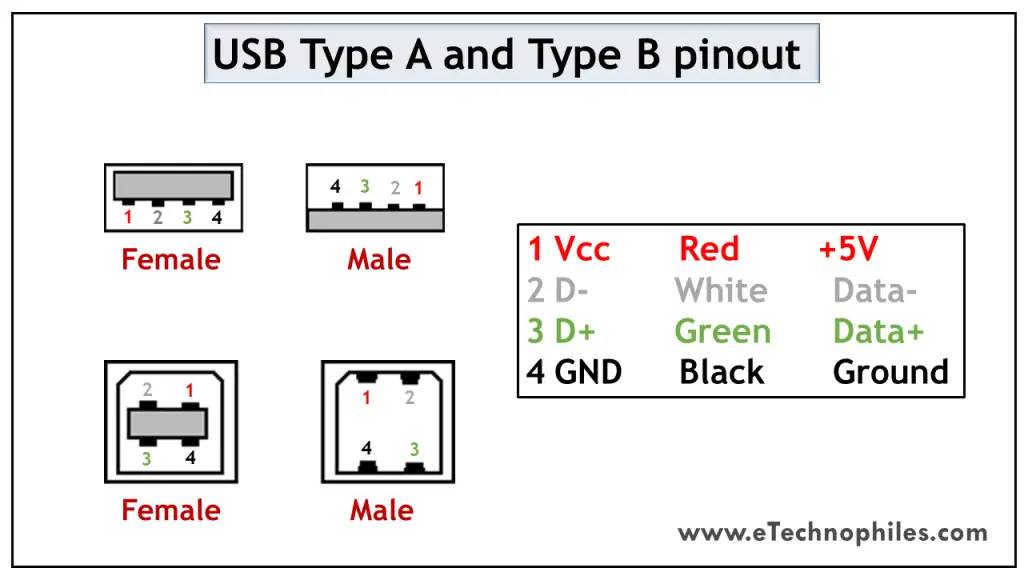
Both these USB types differ in purpose and shape, but their pin connections are the same. Pin 1 is dedicated to the supply and pin 4 is for ground connection. Even pin 2 and 3 take the data input in both these types.
The female port has the PINs in descending order, starting from the right-hand side, while the male connector has them in the reverse order. The table below shows the pinout of both USBs.
USB mini A and mini B
USB Mini was the first improvised version of the normal connectors. This version was launched for both Type A and Type B.
It’s a smaller version of Type A and B, which was extensively used with old mobile phones. The Mini B connector is more popular than the Mini A. The figure below shows the pinout of USB Mini B.
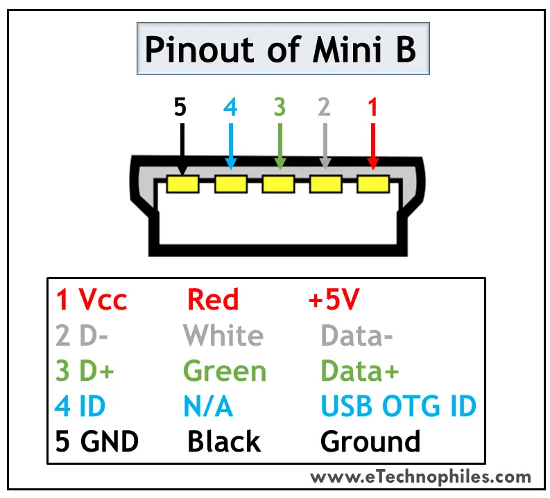
USB Mini B is thinner and more compact than Mini A. Hence it is used for PDAs, digital cameras, etc. Another significant development imposed on Type Mini is that it has an additional pin to support On-the-GO (OTG) connection. Thus it has 5 pins. The pin connections are given in the table below.
USB micro A and micro B
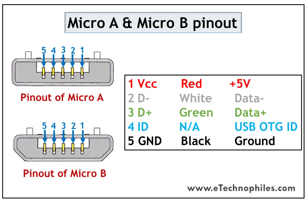
USB Micro is thinner and gives a higher data transfer speed than the USB Mini. It is often used for charging portable devices and comes in two shapes. Micro A is rectangular whereas Type Micro B has a camper shape.
The USB Micro also has 5 pins similar to that of the USB Mini, where the additional pin supports OTG connectivity. The table below shows the pinout of Micro-A and B.
USB standard 3
USB Standard 3 is widely known as the SuperSpeed Mode that brought a revolution in USB manufacturing. The models used in the third generation are highly advanced, offer faster data speed, have a compact design, and are easy to handle.
Features of USB standard 3
The standard 3 models are accepted globally due to the following benefits:
- It is capable of transferring data with a speed of 5Gbps and above.
- Since separate unidirectional paths are used to transmit and receive data, it has a larger bandwidth.
- With predefined power management states, it offers better power management.
- It allows the devices to notify about the data transfer, thereby improving the bus usage.
Standard 3 connectors come in the same physical configuration but with an additional 5 pins to handle these advancements. It includes additional ground and dedicated pins for transmission and reception which are called super-speed connections. ( learn more )
The pinout diagrams of the superspeed versions of different USB types are described in the following section.
USB type A 3.0 and type B 3.0
As discussed above, the normal Type A and Type B connectors have 4 pins. But the superspeed versions of Standard 3 have 9 pins which are visible in the figure below.
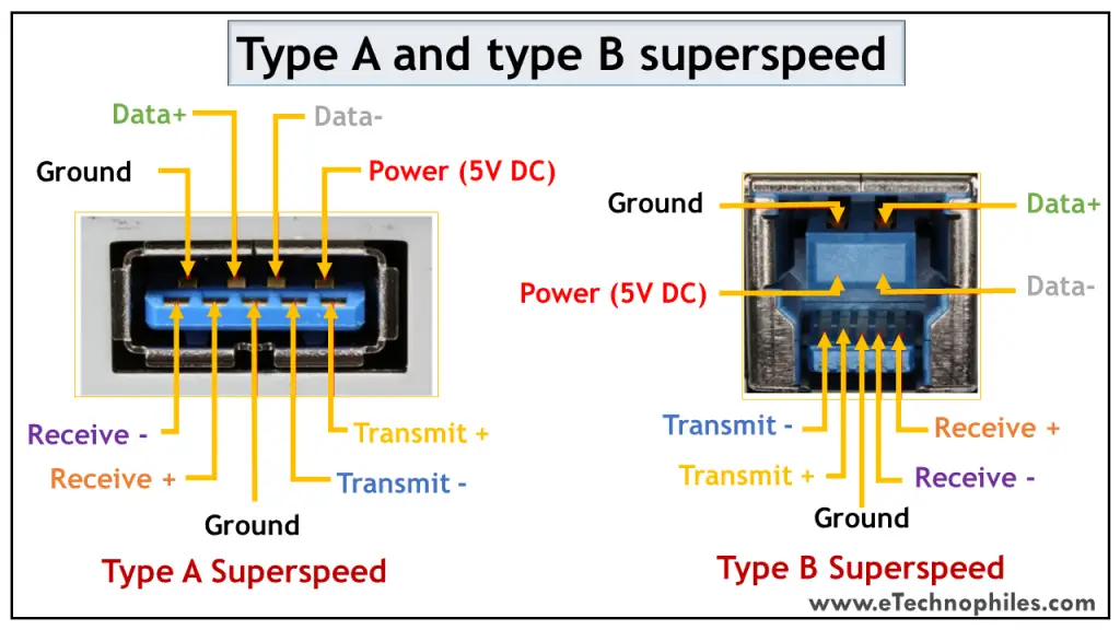
The table below shows the pinout of the superspeed versions.
Micro B 3.0
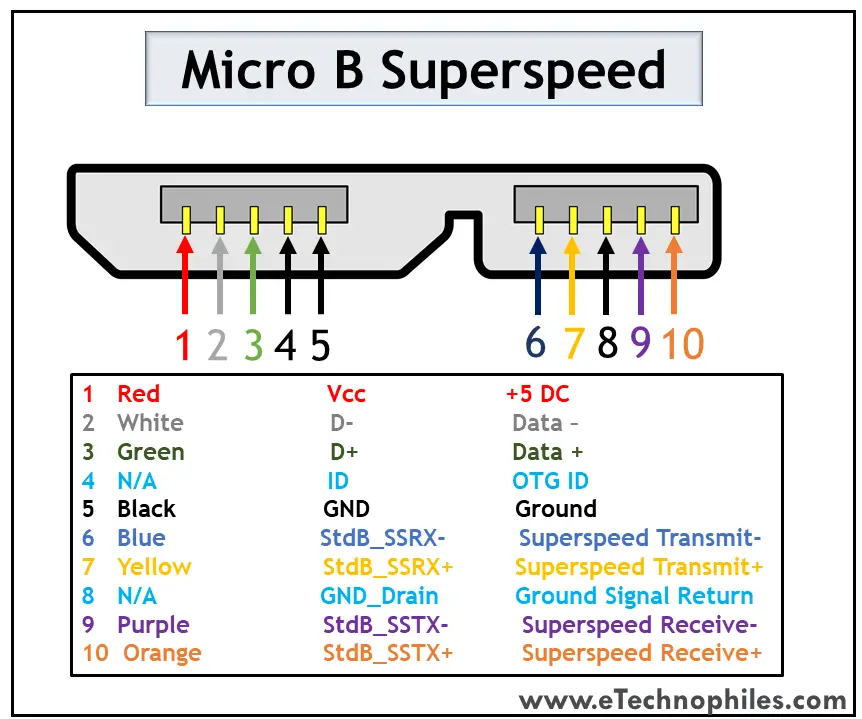
The superspeed version of Micro USB was introduced to Type B. Apart from the existing structure, the five additional pins are placed as an extension. Thus, it has a wider structure. The pinout of the Superspeed Micro B USB connector is given in the table below.
USB type c 3.0
Type C has been the game-changer among all the USB types. It supports data transmission as well as power delivery. Thus, it has become a universal connector for modern devices.

The major attraction of Type C USB is that it is flippable. The figure above shows the pin connections with their corresponding color. The pin connections at the top and bottom are similar, so we don’t have to bother to insert the connector in the correct direction.
It has an incredible data transfer speed of up to 5Gbps and is capable of replacing Ethernet ports to achieve higher data rates. The connection description is given in the table below.
Blessy C Simon
2 thoughts on “10 USB Pinout Explained- USB A, B, C(Male and Female)”
Great knowledge about USB… Thank you
Glad to be of help.
Leave a Comment Cancel reply

USB 3 (Type B) pinout
Usb 3 micro-b pinout.
- rs232 software
- rs232 pinout

- Electronics
USB Pinout | USB 2.0, USB 3.0, Type A, Type B, Mini-B, Micro-B, USB-C
- April 12, 2024
- By Leela Prasad
Universal Serial Bus or simply USB is a popular computer interface that we use to connect a variety of peripherals and devices. Some of the things that we connect using USB are Mice, Keyboard, Printers, Game Controllers , Audio Devices, and many more. Apart from computing devices (laptops, tablets, mobile phones), you can find USBs in cars, bikes, power banks, LED Lights, chargers etc. Depending on the type of application and need, there are several USB ports (USB Type A, Type B, micro-USB, Mini-USB, Type-C etc.). If you are working on anything related to USB, then a knowledge of the USB Pinout is crucial.
In this guide, let us take a quick look at the popular USB Ports and their pinouts. If you are interested in learning about different types of computers ports, then take a look at this 16 Different Types of Computer Ports guide.
A Brief Note on USB
Before the development of USB, we had to deal with separate ports for different types of devices. For example, mice and keyboards had PS/2 Ports, Modems has Serial Ports, Printers had Parallel Ports to name a few.
But with the introduction of USB, this has changed completely. You just need a single port to connect all the aforementioned and many other peripherals and devices to a computer.
From an end-user’s perspective, USB is an easy-to-use interface that supports many devices, is hot pluggable and no fiddling with configuration or settings. You plug-in a device and it just works.
All is not good and positive about USB. There are some negatives as well. For example, the main problem with USB is the different types of connectors it has for different devices (USB A, B, C, Micro, Mini etc.).
This is now changing with the development of USB Type C. We can use USB-C for data transfer, power and charging, connecting to displays, docking stations, etc. with a variety of devices (laptops, smartphones, tablets, computers, cars, external drives, power banks etc.). We believe that USB is finally living up to its “Universal” name with USB Type C.
Different Types of USB Ports
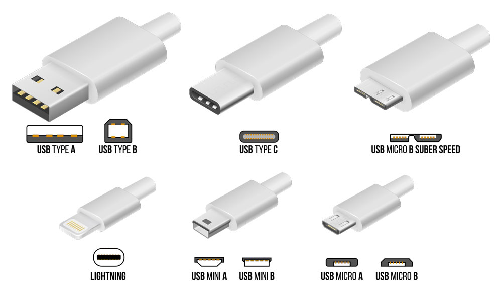
We can divide USB connectors and ports into three types: Type A, Type B and Type C. In both Type A and Type B, there are again three different sizes of connectors intended for different classes of devices. They are: Regular, Mini and Micro.
The connectors are also different based on the version of the USB i.e., USB 1.1 and USN 2.0 have a similar connectors and ports but when it comes to USB3.0, they are completely different. USB Type C sorted this whole mess with a single connector.
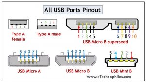
Before looking at the USB pinout of different USB ports, here is an image of all the USB Connectors.
Let us now take a look at the pinouts of different USB Ports. We are mentioning the USB Pinout only for the female side of the connection. The pinout of the male side will be identical except that it will be a mirror image of the female side.
USB is the most popular type of connector at the moment. With USB Type C, it is very close to achieving the true “universal” stature for data, power display and many more. In this guide, we saw the basics of USB, different types of USB ports, USB Pinout of different connectors and receptacles.
Related Posts:
- Can USB Port be Converted to HDMI?
- 16 Types of Computer Ports and Their Functions
- Micro HDMI Vs Mini HDMI
- What Are the Different USB Types?
- What is USB C? (Introduction, Versions, Pros and Cons)
- What Is A Docking Station
Leave a Reply Cancel reply
Your email address will not be published. Required fields are marked *
Get our Latest Newletters
Get great content that you love. No ads or spams, we promise.

Tutorials Symbols Courses Calculator Deals
Electrical Electronics Embedded Power Robotics ARM IOT
Mini projects Microcontroller Arduino Solar Free circuits Home Automation Seminar Topics Electronics Questions
Capacitors Resistors Filters Diodes Transistors Amplifiers IO Devices Thyristors DC Circuits Number System
Your Privacy is important to us
Tutorials Symbols Courses Calculator
- Affiliate Disclosure
- Terms and Conditions
- Privacy Policy
Copyright © 2024 Electronicshub.org

- PCB Quote Prototype PCB Instant Quote Mass production PCB Instant Quote -->
- PCB Assembly New --> PCB Assembly Quote PCB Assembly Service PCB Assembly Process
- BOM Service
- Components Sourcing Hot

- Gerber Viewer | DFM Free Online Gerber Viewer HQDFM Design Analysis Software
Support Team
0086-755-83643663
+86 15013838486

USB Pinout: Everything You Need to Know
Introduction to usb pinout.
USB connects computers, smartphones, printers, cameras, and more. It has become a common data transport and charging interface since 1996. USB's pinout, which controls how the connector's pins transport data and power, is crucial.
USB pinout connects and transfers data. Its pins transfer data, provide power and determine device orientation. Several USB connectors have different pin configurations. Type-A, Type-B, Mini-USB, and Micro-USB connectors are the most popular.
The most prevalent USB connector on computers and chargers is Type-A. It has two power and two data pins (D+ and D-) (VCC and GND). Printers, scanners, and other power-hungry equipment employ Type-B connectors. It contains five pins: two data, two power, and one ground.
Cameras, smartphones, and tablets employ Mini-USB and Micro-USB ports. They have a ground pin, two data pins, and two power pins. These connectors are more compact than Type-A and Type-B connectors.
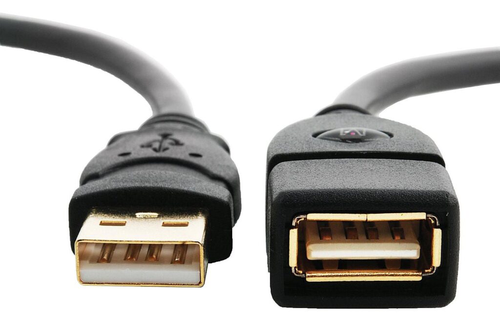
USB pinout is crucial for data transfer, charging, and device performance. The pinout limits data transfer speed, power, and data type. So, understanding USB pinout is essential for troubleshooting and device communication.
Data transport and charging depend on USB pinout. Knowing USB connector types and pinouts helps troubleshoot and ensure device communication. To maintain device connectivity, keep up with USB pinout changes as technology evolves.
Understanding USB Pinout
USB pinout is the connector's pin configuration and how it transfers data and power. Each USB connector has a unique pinout and function. Depending on the connector, USB has four or five pins. Type-A, Type-B, Mini-USB, and Micro-USB connectors are the most popular.
The most popular USB connector, the Type-A, contains four pins: two data pins (D+ and D-) and two power pins (VCC and GND). Power pins power devices, whereas data pins convey data.
Printers, scanners, and other power-hungry equipment employ Type-B connectors. It contains five pins: two data, two power, and one ground. The Type-B connector contains a ground pin and data and power pins like the Type-A connector.
Cameras, mobile devices, and tablets frequently use Mini-USB or Micro-USB charging and data transfer connections. Two power pins, two data pins, and a ground pin make up the standard configuration for these ports. Mini-USB and Micro-USB connectors have fewer data and power pins than Type-A and Type-B connectors.
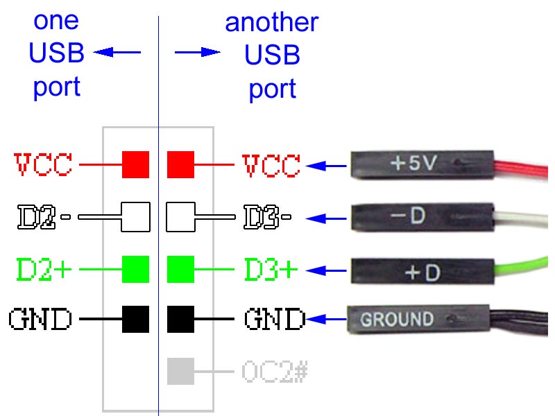
USB connector data pins transfer digital signals. D+ and D- pins encode and decode data when transmitting. DC voltage powers linked devices through power pins.
USB pinout defines the connector's pin layout and how they transfer data and power. Troubleshooting and device connectivity require knowledge of USB connector types and pinouts.
USB Data Transfer
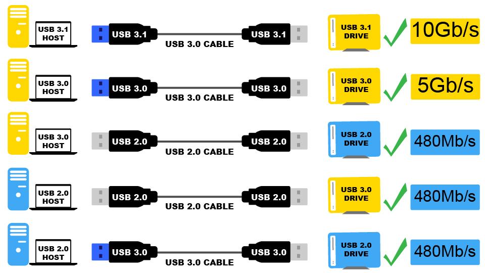
USB data transmission is the process of exchanging information between two USB-enabled devices. Information stored digitally can take many forms, from static images to moving ones. The USB protocol defines the rules for data transfer between devices connected via USB.
The USB protocol's multi-layered architecture comprises the physical layer, data link layer, and application layer. Together, these layers provide error-free information exchange between gadgets. The USB cable and connector are part of the physical layer, which also specifies the signal's electrical characteristics. While the application layer specifies the nature of the data being exchanged, the data connection layer controls how that data moves between devices.
Bulk transmission, interrupt transfer, isochronous transfer, and control transfer are the many types of data transfer available over USB. While interrupt transfer is used for inputs from the keyboard and mouse, bulk transfer is utilized for larger data transfers like file transfers. Real-time data transfers, such as audio and video streams, employ isochronous transfer whereas device configuration and status updates use control transfer.
USB speeds vary by version. And USB 2.0 has 480 Mbps data transfer, while USB 1.1 has 12 Mbps.
USB 3.2 allows 20 Gbps data transferring speed. USB data transfer speed and reliability depend on USB cable quality. Several lengths and types of Type-A, Type-B, Mini-USB, Micro-USB, and USB-C cables are available.
USB Power Delivery
USB Power Delivery (USB-PD) lets devices charge faster through USB cables. USB-PD uses USB Type-C connectors and cables and extends the USB standard. The USB-PD protocol allows the host and device to negotiate power, delivering up to 100W across the USB cable. This is a big boost over USB 1.0 and 2.0's 2.5W and USB 3.0's 7.5W.
The USB-PD charges several devices simultaneously, laptops, and other high-powered devices faster. USB-PD lets devices negotiate power for optimal charging.
USB-PD supports USB Type-C connectors, a major benefit. Reversible USB Type-C connectors are easier to use. They can charge laptops and other high-powered gadgets due to their increased data transmission speeds and 100W power output.
USB Power Delivery also powers screens and connects peripherals. USB-PD powers screens without a power cord. USB-PD powers and connects docking stations and external hard drives.
USB Power Delivery lets devices charge faster using USB cables. USB Power Delivery uses USB Type-C connectors and cables and extends the USB standard. USB-PD charges several devices simultaneously, laptops, and other high-powered devices faster. USB-PD may also power screens and connect devices.
USB Pinout Diagram
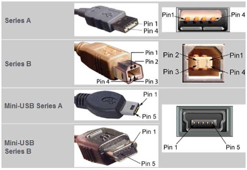
A USB cable's wiring and connections can be visualized with the help of a pinout diagram. Type-A, Type-B, Mini-USB, Micro-USB, and USB-C are just a few of the varieties of USB connectors available. Pinout diagrams, which display the configuration and functionality of connectors, are specific to each variety.
USB Pinout: Type-A
The most used USB connector is the USB Type-A connector, which is used to link peripherals to a computer. The USB Type-A pinout consists of four pins labelled VBUS (power), D+ (data), D- (data), and GND (ground). The data transmission occurs between the device and the computer via the D+ and D- connections, while the VBUS pin provides power to the device. Electrical ground is provided through the GND pin. If you're having problems with your USB connections, data transfer, or power delivery, studying the USB Type-A pinout diagram should assist.
USB Pinout: Type-B
The USB Type-B connector is commonly utilized on devices like printers and scanners that are linked to a computer. The pinout diagram for USB Type-B comprises five pins, including VBUS (power), D+ (data), D- (data), GND (ground), and ID (identification).
USB Pinout: Mini-USB
The Mini-USB connector is a more compact version of the USB Type-B connector. This connector is frequently found in mobile phones and other portable electronic devices. VBUS (power), D+ (data), D- (data), GND (ground), and ID are the five pins that are included in the pinout schematic for Mini-USB (identification).
USB Pinout: Micro-USB
USB connector is a smaller variant of the USB connector and is often utilized on small devices such as smartphones. It has five pins in its pinout diagram, which are VBUS (power), D+ (data), D- (data), GND (ground), and ID (identification).
USB Pinout: USB-C
Newer devices have USB-C connectors. It provides speedier data transfer and charging and may be plugged in either direction. USB-C has 24 power, data, and miscellaneous pins.
In conclusion, USB pinout diagrams provide a visual representation of a USB cable's wiring and connectors. There are numerous varieties of USB connectors, and each has its own pinout diagram. Understanding these diagrams might be useful for debugging USB connection problems or developing and constructing USB devices.
Troubleshooting USB Connections
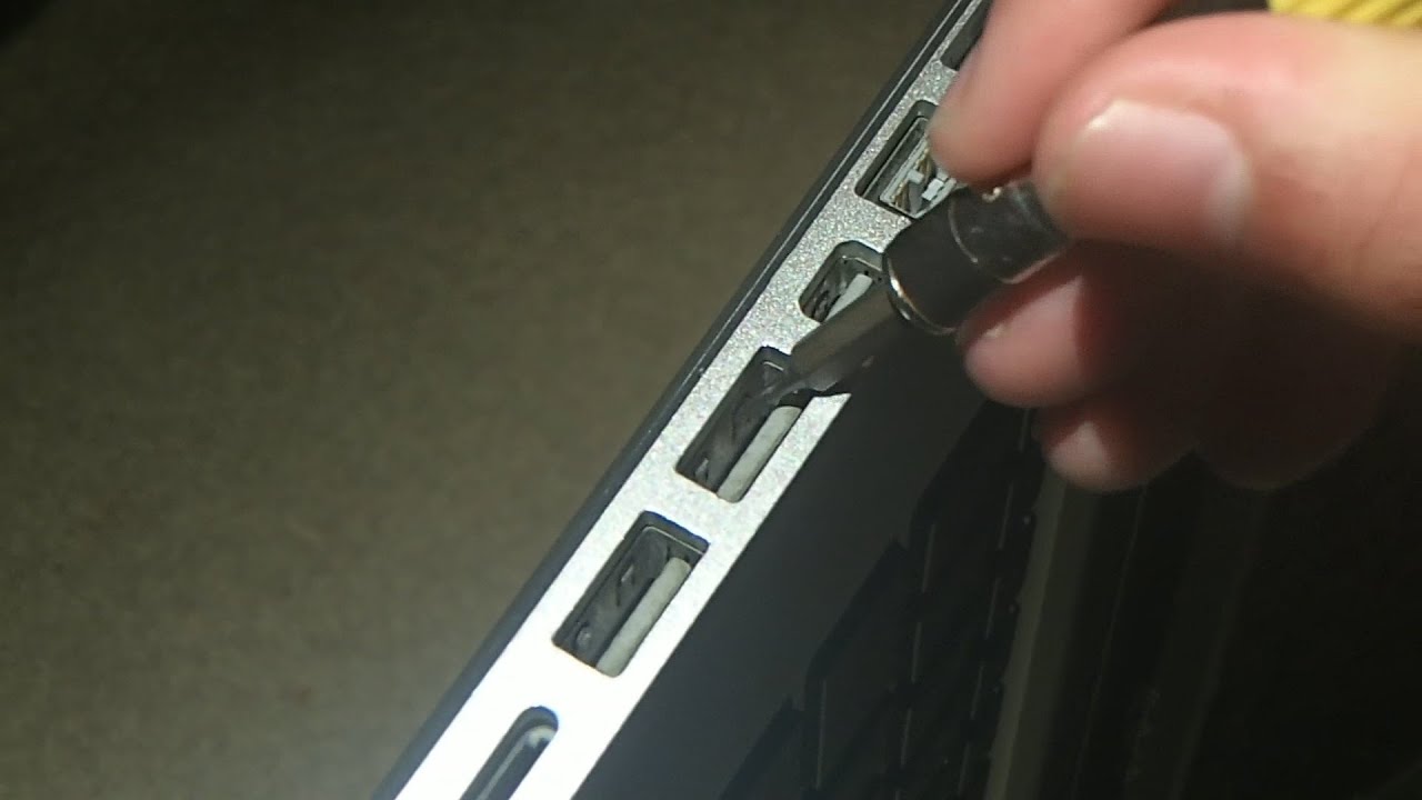
Connection, data transfer, and charging issues are just some of the issues that might arise from a faulty USB pinout. To fix USB pinout problems, use these troubleshooting steps:
Step 1 - Check the condition of the cable
Make sure the USB cable you're using isn't broken and is in good working order. Worsening connection and data transfer challenges are bent or broken pins or cables. If the issue remains after trying a different USB cable, it may be time to call IT.
Step 2 - Check the USB port that you going to connect
Checking the USB port you're connecting to is the next step when resolving USB pinout difficulties. Verify that the USB port is undamaged and working properly; a broken USB port might disrupt connections and prevent data from being transferred. Swap out the USB port on your computer or gadget to see if that helps.
Make sure the gadget you're trying to connect is configured to work with the proper USB settings by checking its settings. USB connections and data exchanges might be affected by the various configurations available on various devices. Verify the right configuration of the equipment by consulting the handbook or the settings.
Step 3 - Check the power of the USB port
It's crucial to verify the device's power supply when addressing USB pinout difficulties. Verify the power supply if the USB device is not charging or is not getting enough juice. Verify that the gadget is set up to accept power through USB and that the power source is providing sufficient power. Problems with charging or powering may occur if the USB device's power needs exceed those of the present power supply. These problems may be fixed by checking the power supply and making any necessary modifications.
Step 4 - Check your device drivers are up to date
If you're having problems with the USB port, one good step is to see if there are any updated drivers available. Verify that you have the most recent USB drivers installed on your PC or another device. Problems with connectivity and data transfer can be caused by using outdated drivers. Check the manufacturer's website for updated drivers, and apply them if they're available. If your computer or device isn't fully compatible with the USB device you're trying to connect, this should help fix the problem and allow the devices to communicate.
Step 5 - Finally check with a different device
Testing the USB device on a different computer or device is a helpful troubleshooting step when dealing with USB pinout difficulties. Seeing if the issue persists after connecting the USB device to another device is one possible solution. If the USB device is functional with another computer or device, the issue may lie with the drivers or settings on your computer or device. This can help you zero in on the precise nature of the problem and get to its origin so you can address it effectively.
USB pinout difficulties can be frustrating, but there are various ways to fix them. Examining the USB cable, port, device USB settings, power source, and driver updates, and testing the USB device on another computer or device will help you find and fix the problem. These actions will ensure your USB devices work properly and prevent further troubles. To avoid future troubles, update your computer's USB drivers and utilize high-quality cables and devices.
The USB pinout is a crucial component of USB technology, facilitating accurate data transfer and power delivery among devices that use the USB standard. Familiarity with USB pinout diagrams and troubleshooting USB pinout issues can help you diagnose and resolve problems with USB connections, data transfer, and power delivery. Understanding the USB pinout is essential for maximizing the potential of USB technology, whether you are developing and constructing USB devices or utilizing USB technology to connect and charge your devices.
You may also be interested in...
- Transistor Pinout - Everything You Need to Know
- VGA Connector Pinout - Basic Introduction is Here
- Free PCB Assembly Offer is Now Live: Experience Reliable PCB Assembly from HQ NextPCB
- HQ NextPCB Introduces New PCB Gerber Viewer: HQDFM Online Lite Edition
Still, need help? Contact Us: [email protected]
Need a PCB or PCBA quote? Quote now
- PCB Prototype
- PCB Assembly
- SMD Stencil
Recommended Article:
- Raspberry Pi 5 as a Home Automation Hub: The Future is Now
- What You Need to Know About BGA Soldering
- HQ NextPCB of HQ Electronics Showcases it’s Services at IPC APEX 2024
- Introduction to Via in Pad Technology
- Find HQ NextPCB at the biggest PCIM Europe Exhibition Ever for the Power Electronics Industry
- How to avoid shorts and opens in PCB Design using Design for Manufacture (DFM) tools?
- Gerber Files for PCBs: Creating, Viewing, and Converting
- Printed Circuit Board Basics: From Design to Final Artwork
- The Four Major Bare PCB Test Methods
- PCB Design Fundamentals
- Exploring HQ NextPCB's Free Gerber Viewer: A Handy Tool for Easy PCB Design Analysis
- Consequences of insufficient spacing between components for surface mount assembly
- What Is an FET (Field-Effect Transistor)?
- DFM, DFMA, DFA. Part 2. NextPCB's PC program
- What is Open Circuit?
PCB Manufacturing
Rigid-flex pcb.
- Heavy Copper PCB
- High Frequency PCB
- High Tg PCB
- Metal Core PCBs
- Aluminum PCBs
- Rogers Material
PCB Assembly
- Custom Cable Assembly
- Custom Wiring Harness
- Capabilities
- Pad Hole Ring Copper
- Pad Hole Ring Copper Specification
- Your Name *
- Phone Number *
- Tell us your needs (as specific as possible) *
- File (Gerber files and BOM need to be compressed into one ZIP file.)
Contact WellPCB Team
Usb pinout: the beginner’s guide.
Nowadays, it’s easy to complete projects that involve creating a physical connection between a host controller and several other bus-powered devices because of the USB interface.
USB stands for Universal Serial Bus and has since replaced its predecessors (FireWire, RS-232 serial, and even parallel) as the primary interface for connecting a host to a device.
Normally, the architecture of a USB system includes a host controller, USB ports, and a wide variety of devices. Also, there are cases where you can add additional USB network hubs to create a tree connection structure.
However, that’s just the surface of it all.
So, in this article, we’ll explain everything about the USB and give different USB examples for your circuits.
Let’s begin!
USB Flash drive
The USB has four shielded wires that work as pins. Two of these wires are for power supply, while the other two are for differential data signal pairs. Check out the table below for the full USB pinout.
How Does a USB Work?

plugging a USB pen drive on a laptop
Like all connectors, all types of USB connectors have male and female types, making sure you connect your devices in the right direction.
It’s essential to make correct USB connections to allow the system to follow the required USB protocol. So, to establish a connection, USB remote devices feature what we call an upstream connection. These remote devices use this upstream connection to connect to a host.
Now, the hosts also have downstream connections that allow them to connect to the remote devices.
Furthermore, you can’t use upstream and downstream connections interchangeably. This helps you avoid misconnections and makes sure you connect the USB cable only in the right direction.
It also helps you avoid several issues like illegal loopback connections and connecting a downstream port to another downstream port.
How it really Works
First, a USB device will show its maximum speed by using pull-up resistors to draw the “D+” and “D-” terminals to 3.3V. Now, the host or hub will also use these pull-up resistors to detect when you connect a compound device to its port. Thus, without a pull-up resistor, the USB won’t detect your connected device or if you have a broken device or broken connector .
So, when you plug in an external device for the first time, the host device scans it and loads the correct driver version required to run the device. To do this, the host uses a product ID/vendor ID (PID/VID)—which the connected hardware or device supplies. Once the host completes the loading of necessary device drivers, the hardware/device will be ready for use.
Note: USB host controllers have their specifications. We have the Universal Host Controller Interface (UHCI), which works for all USB types, the Open Host Controller Interface (OHCI), which works with USB 1.1, and the Enhanced Host Controller Interface (EHCI), which works with USB 2.0.
USB Connector Types
Originally, the USB cable could only be one of two types, and these two types included “Type A” and “Type B”. Afterward, we got the USB C type, which boasted a better data transfer speed with a more robust system.
Check out the table below for the full overview of the different USB types.

Type-A USB Connector Pinout
Type-A USB is the most popular type of USB connector. Plus, you can find them on host controllers, computers, flash drives, and several other items. Also, you can only make downstream connections with the Type-A USB as its sole use is for controllers and hubs.
Flash Drive
Type-A USB connectors are bigger than other connectors and have flat and rectangular shapes. Plus, friction holds this connector in place, making it easy to connect and disconnect. However, using it in areas where your equipment might vibrate isn’t a great idea.
The Type-A USB has two versions: Male and female versions. The male version is the plug, while the female version is what we know as the socket or port.
Female connector versions are what we find on host controllers, while male connector versions are usually on devices like memory sticks, keyboards, mice, and other connections to storage devices.
Applications.
- Works in most personal computers.
- Also works in television and music systems.
- You can also find them on gaming consoles and almost all chargers for mobile portable devices.
Type-A USB Pinout
The older versions of the Type-A connector have four pins, while the newer versions have nine pins. Here’s a table showing all the pins of the Type-A connector.

Note: all generations of the Type-A USB connector have pins 1 to 4 while third-generation connectors have pins 5-9.
USB-B Pinout
The USB-B is the second connector type that mostly works for connecting peripherals like printers and scanners. Plus, their pinouts have a different arrangement.
It has an almost square shape with a slight bevel at the top end corners of the connector. Also, it uses friction to remain in place when connected.
The Type-B USB port is an upstream connector that you can only find on peripheral devices. Thus, most Type-B USB applications require A to B USB cables.
Here’s an interesting fact:
Type-B USB canceled out the chances of creating a connection between two host computers. Thus, helping to prevent damages.
This connector mainly works for peripherals like printers and scanners.
Like the Type-A USB, the older versions of Type-B have four pins, while the newer 3.0 versions have nine pins. Here’s a table showing all the pins:

Also, there is a second type of Type-B connector that has two extra pins:
Source: Wikimedia Commons
USB-C Connector
The USB Type-C is the USB specification that’s slowly replacing the USB-B. It’s a tiny 24-pin reversible plug that works for USB cabling and devices.
Type-C USBs can serve as connectors for both hosts and devices. Plus, you can find Type-C USBs in most recent mobile devices.

USB-C Connector Pinout
The Type-C USB has 24 pins which you can connect reversibly. Here’s a table showing the full list of pins:

Micro USB Pinout
A smaller connector became necessary as the technology required smaller USB sizes for many items like modern mobile phones and audio devices. Thus, the USB Microcontroller was born.
The micro USB has both Type-A and Type-B USB versions available, like the 1.0 micro-USB and 2.0 micro-USB. However, these versions are smaller, and you can use them for much thinner lines of equipment.
Additionally, the micro USB is the USB standard and offers better transfer rates from an external source.
Standard older micro USB connectors have five pins, while the less common 3.0 version has ten pins. Here’s a table showing the pins of the micro USB connector:

The fourth pin mode is what we call the USB on-the-go (OTG). It allows you to switch between the peripheral and host roles on your devices. It’s also what enables devices to decide which will act as a power source once connected. For instance, plugging an android phone into a laptop. The laptop will charge the phone if you have a charge-only cable, not the phone charging the laptop.
Wrapping Up
It’s worth mentioning that sometimes, it’s possible to use USB A to USB A cables to establish connections between a computer or USB device to another USB device with an A-style female port. So you can transfer data between both systems.
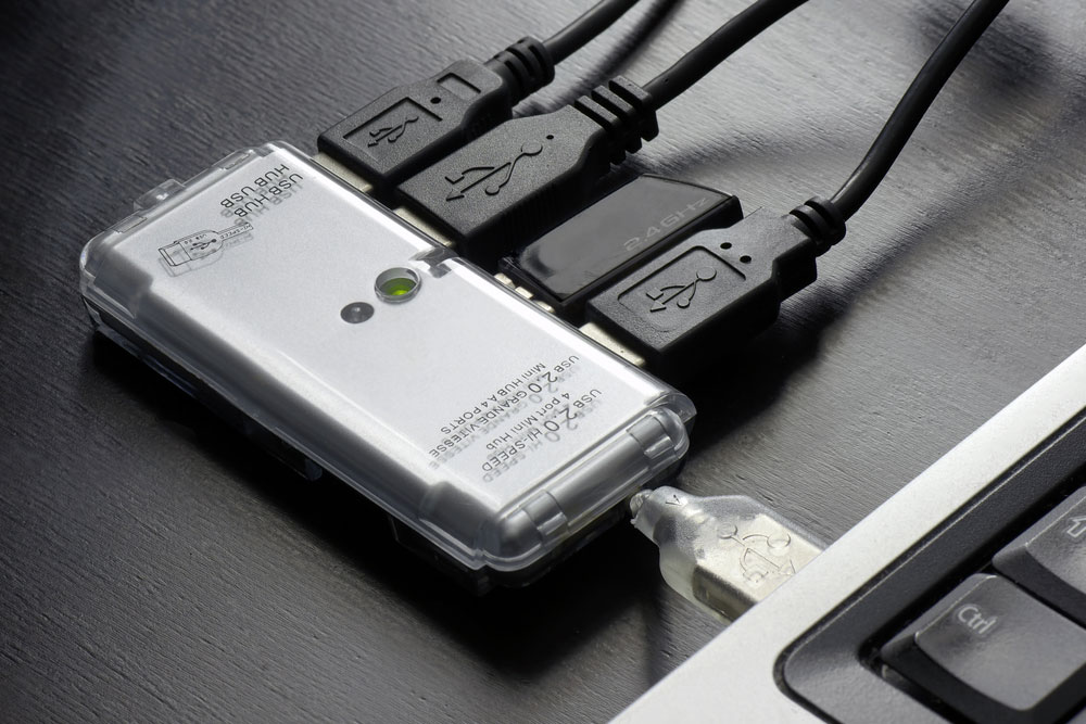
However, you shouldn’t use the type A to A cable connection to create connections between two computers or a USB hub and two computers. Why? Well, creating such a connection would mean the cable would receive equal amounts of voltage (5V) from both computers. Thus, connecting both power supplies and causing irreparable damage and other issues. Sometimes, it may even cause a fire hazard.
Well, that wraps up this article. Feel free to reach us if you have any questions, and we’ll be happy to help.

Cras quis nulla commodo
Circuit board fabrication and pcb assembly turnkey services.
To enhance your browsing experience, we use cookies. These cookies may contain your personal information. Please review our Privacy Policy for more information.By clicking "Agree," you acknowledge that you have read and agree to our Privacy Policy and the use of cookies. You can manage cookie preferences anytime in your browser settings.
Get 3 pieces of PCBs for Just $1! 🚀
- 👉 Choose between one or two-layer PCBs.
- 👉 Available in a variety of colors and thicknesses.
- 👉 Board dimensions must be within 100 x 100mm.
Stack Exchange Network
Stack Exchange network consists of 183 Q&A communities including Stack Overflow , the largest, most trusted online community for developers to learn, share their knowledge, and build their careers.
Q&A for work
Connect and share knowledge within a single location that is structured and easy to search.
How many ports can a 20 pin usb3 header support?
If I have a 20/19 pin header on a motherboard or pci-e expansion card, how many actual usb ports does this support?
I've seen most recommend 2 ports per header.
However, a product like this would seem to support 4 ports with one header: http://www.tendak.com/index.php/Product/show/id/116.html
3 Answers 3
Intel had defined that header as providing two USB 3.0 ports. There aren't enough pins for more ports.
http://www.intel.com/content/dam/doc/technical-specification/usb3-internal-connector-cable-specification.pdf
From page 8 of the spec linked above:
2.1 Signal Descriptions and Pin Assignments […] Figure 2-1 illustrates the USB3 ICC pin numbering. Note that the connector include[s] two USB ports. [Figure 2-1 shows a 19-pin header connector pinout] Users may choose to include more or less USB ports by expanding or reducing the pin and wire counts. This document covers only the base unit with two USB ports.
That product you linked to apparently has a built-in USB 3.0 hub (or two) to allow it to provide additional ports. The site even calls it a "front panel USB hub ".
The 20 pin usb 3.0 connector socket passively allows two usb 3.0 female type A sockets two be wired in...
With the use of active "hub" you could split these 2 physical connections into multiple connections... But as with all active adaptations... Latency will be introduced; you'll be introducing a "middle man" (or you know another PCB) between your usb 3.0 devices and your motherboard...
Sticking to the physical limitations of your motherboard and running only 2 x usb 3.0 females type A to every usb 3.0 20 pin female motherboard socket will yield best performance...
The usb 3 header can provide 2 usb2 headers. Therefore a usb3 header can provide 4 usb2 ports or 2 usb3 ports without a hub.
- no it doesnt. A usb3 header can provide 2 usb2 header, which then allows 2x2 or 4 usb2 ports. Where did anyone say that before? I know it is true, it is a cable only, no hubs and works fine. MODDYI sells it – philhu Mar 23, 2018 at 15:45
- Source for the 2x2 claim? It is true that a normal USB2 header would support 2 ports, but a splitter isn't exactly the kind of "usual" thing you could apply common wisdom to. I do have one myself for instance (it's for USB2 by MZHOU, and not modDIY, but still) and while it can "merge" two physically different cables/sources.. you'd better hope none of them offered/used two ports because only one will work on each end of the Y. Then, I'm not an electrical engineer, but the spec seems to suggest similar behaviour to USB3. – mirh Apr 3, 2023 at 22:33
You must log in to answer this question.
Not the answer you're looking for browse other questions tagged usb-3 ..
- The Overflow Blog
- How to prevent your new chatbot from giving away company secrets
- Introducing Staging Ground: The private space to get feedback on questions...
- Featured on Meta
- Testing a new version of Stack Overflow Jobs
Hot Network Questions
- Will this short circuit to turn off an LED drain the battery?
- How can a point source emit spherical EM waves when they are forbidden by Maxwell's equations?
- What is the meaning of existence?
- Is there theological significance regarding the way different translations render Jesus’ words in Matthew 16:13?
- Problem in block diagram
- Is there a paradox in the proof of Godel's incompleteness theorem?
- Is rolling resistance that significant?
- How are wallpapers unlocked?
- Is there an expression that can be used to evaluate the threshold that characterizes a substantial difference between sample means for t-test?
- How do I write from a male's POV?
- How can I access SQLCLR assembly functions in MySQL
- Given two vectors, how to find that the vector A is a subset of the vector B, including the repeated values?
- Explain to a non-physicist what goes wrong when trying to quantize gravity
- Calculation time too long for FoxH
- How to deal with monitoring software on a personal PC used for work?
- How do I stop wasting time on Reddit at work?
- If Trump pardons himself regarding the federal crime he tried to hide by cooking the books, is the New York conviction void?
- What happens if two reviewers have incompatible recommendations for a paper?
- Help me unlock an old laptop
- Are there any *real* reasons not to long hold leveraged ETFS like TQQQ?
- What does "Belgian" really mean, in the Fast and Furious series?
- I don't get how the “edge angle” node works
- Looking for pulp sci-fi paperback written pre-1976, two men, separated early in the book, find an underground civilization of dim-witted, pale beings
- What incentivizes governments to address problems the public is ignorant about, such as superbacteria or open DNS servers?
USB C Pinout – All USB 2.0-3.0 Type Pin Diagram
Blog , Circuits
For those with a passion for technology and having an interest in the detail workings of modern connectivity, understanding the USB-C pinout is like uncovering the blueprint behind this remarkable connector. In this article, we will explore the vast and interesting detail of USB-C, which is serving to the modern electronics and to the tech enthusiasts, hobbyists, and engineers. Unraveling the complexities in simple words, and exploring the boundless possibilities it enables.
The USB C connector nowadays is most commonly used for charging mobile phones and various other portable devices like Bluetooth headset, Bluetooth speaker, Mini drones, Power Banks and various other tech gadgets not limited to emergency lights, LED decorative lamps.
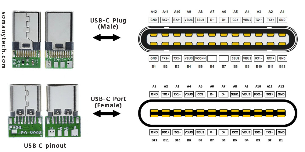
To the left in the above image are USB connectors with board as a USB 2.0 mode utilization, (D+, D-, VBUS, GND). Note that the USB 3.0 are fully functional cables connections are implemented with 8 or 10 connecting wires/bus.
The 24-pin double-sided connector offers a USB-C port that measures 8.4 x 2.6 x 6.65 mm. The 8.4 millimeters (~0.33 inches) is its width, the 2.6 millimeters (~0.10 inches) is its height, and the depth of 6.65 millimeters (~0.262 inches). The dimensions are for the internal side of a receptacle and outer side of a plug. And for more details refer to the datasheet provided by the manufacturer. These connectors come in two forms: a male/ plug and a female/ receptacle. (see image above)
The Plugs are commonly found on cables and adapters, providing the means to connect devices. On the other hand, receptacles can be found on devices and adapters, providing a socket for the plug to be inserted into and for establishing connections.
Simplified USB C pinout with their functions are as follows:
The USB C pinout table, offering resources on the intricate details of USB-C connectors. By reading the table, you could understand various pins and their vital functions, enabling a comprehensive understanding of how USB-C devices and cables work together in conjunction.
With careful attention to detail, the table unveils an array of essential pins such as VBUS, GND, CC1, CC2, D+, D- and so on. Each pin have a distinct purpose, from power supply and communication channels to data transmission and more.
It’s a complex network of connectivity enclosing power delivery, audio, video, and alternate modes. As you explore USB protocols, you’ll gain a profound insight of the complex signals and connections within the USB-C ecosystem.
Below is an image showing USB type C 3.0 modules for high speed data communication:
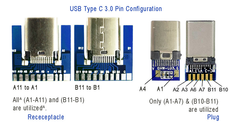
Power: The A4, B4 and A9, B9 are connected to supply voltage. Also A1, B1 and A12, B12 are grounded. Thus, number of pins and wires to GND and VCC are reduced to 2 only.
SBU1, SUB2: These pins are called secondary bus. The A8, B8 are for side-band and are not utilized in USB communication and are reserved for future use. And therefore, the functional pins on each side remains to 9 each.
CC1 or CC2: These pins are used for Pin configuration detection, CC is used for USB-PD, i.e. USB power delivery communication to determine current control to the devices, for example charging current. Generally, CC is connected in series with a Resistor = 56k at port end. Thus, the total wires in the cable is found to be minimum 8 in numbers for functional high-speed USB C 3.0/ 3.1 type.
Also check micro USB pinout and how it is different from type C connectors .
Click here for helpful -> “ wiring diagram for USB 3.0″ high speed data support and device charging .
Below is an image showing USB type C 2.0 modules for older data transfer and charging:
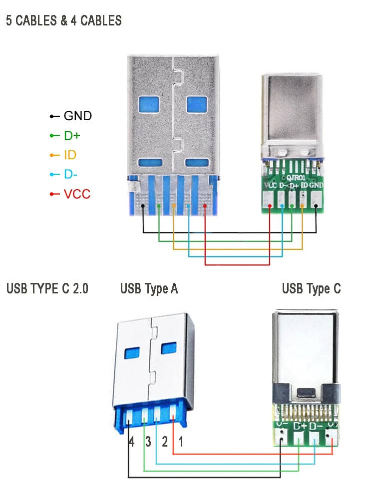
The above image showing the schematic diagram USB type C 2.0 older standard version of mobile phone charging and data transfer cable . Note that there are two types available, one with ID pin and without ID pin. ID pin is sometimes connected to the ground or connected in series with some resistor.
These cable supports both power and data transfer, there are also power only charging cables that support only charging. Meaning, you cannot use them for tasks such as syncing devices, transferring files, or connecting peripherals. They are solely intended for charging purposes. They come with only two connecting wires inside, and they are thicker wires to offer lower resistance to the current flowing though them.
These are made to target devices like neckband/ earphone charging, for charging mobile-phones, USB powered LED lamps and other gadgets that have nothing to do with the data transfer. They are less expensive than the one with data sync capability.
Related Posts

Blog , Component ID
8205A IC Datasheet PDF, Pin-out & Equivalent Mosfet IC
Here is the detailed information on the features, applications, uses, and specifications of this popular and most commonly found dual Mosfet 8205A IC with datasheet. If you are looking for a high current transistor to use in battery protection, load switching, or power management PCB circuit, this Dual MOSFET is designed in a way to […]

Top 11 Best Scientific Calculator App for Android – 2024
Utilize to the fullest the Android phone with the Best Scientific Calculator App, this app is very useful for Students, Engineers, or anyone requiring to calculate large complex scientific calculations which are more time consuming and not necessary to do manually. This powerful tool combines advanced mathematical functions with a user-friendly interface, making it the […]

Circuits , Component ID
IRF540, Datasheet PDF, Specification, Circuits, Pinout, Equivalent, Alternatives
For the high-current switching application, the IRF540 MOSFET is one of the popular choice. The IRF540 stands out for its fast switching, rugged device design, low on resistance and cost-effectiveness. In this article, we have discussed IRF540, check its pinout, equivalent, practical applications, distinctive features, as well as instruction on when and where to employ […]

IRF4905, Datasheet PDF, Specification, Pinout, Circuits, Alternatives
In need of high-current switching application, the IRF4905 MOSFET is one of the preferred choice. The IRF4905 stands out for its reliability and efficiency, making it the preferred selection for applications requiring rapid switching speeds and the power control system. In this article, we have discussed IRF4905, check its pinout, equivalent, practical applications, distinctive features, […]

Privacy policy
We're sorry but your browser is not supported
To ensure the best online experience possible, please upgrade your browser or contact us.
Tel:1-855-326-4757
Email: [email protected]
Subscribe Today & Save 10% on Your Next Order
- Parametric Search
Product Categories
Circuit Protection
Computers and peripherals, electromechanical, kits and tools, led lighting, optoelectronics and displays, semiconductors, test and measurement, thermal management, tools and supplies, wire and cables, ip&e components.
- Electrical Distribution and Protection
- ESD Protection Diodes
- Overcurrent Protection
- Surge protection Modules
- Computer Products
- Kits & Tools
- Connector Accessories
- I/O Connectors
- Connector Other
- Wire and PCB Connector
- Audio Components
- Electromechanical Switches
- Flow & Level
- Mechanical Power Transmission
- Motion Control and Fluid Power
- Capacitive Encoders (82)
- Magnetic Encoders (35)
- Mechanical Encoders (980)
- Optical Encoders (676)
- Clock and Timing
- Data Conversion Development Boards and Kits
- Development Kits and Tools
- Development Systems
- Embedded System Development Boards and Kits
- Flash Cards
- Power Management Development Boards and Kits
- Programmable Logic Development Boards and Kits
- RF and Microwave Development Boards and Kits
- LED Accessories
- LED Displays
- LED Indication
- LED Lighting
- Lighting Fixtures
- Optoelectronics
- EMI/RFI Suppression
- Oscillators & Crystals
- Power Line Filters
- Power Management
- Power Supplies
- Attenuators
- Communication
- Controllers
- Data Acquisition
- Diodes, Transistors and Thyristors
- Electronic Switches
- Microcontrollers and Processors
- Networks and Interfaces
- Programmable Devices
- RF and Microwave
- Standard and Specialty Logic
- Transceivers
- Accelerometers (870)
- Air Quality Sensors (333)
- Ambient Light Sensors (346)
- Angular and Linear Position Sensors (2244)
- Board Mount Pressure Sensors (4555)
- Color Sensors (83)
- Current Sensors (1364)
- Fan Controllers (375)
- Flow Sensors (216)
- Force Sensors and Load Cells (290)
- Gyroscopes (194)
- Hall Effect Sensors (3263)
- Image Sensors (1656)
- Industrial Pressure Sensors (2606)
- Level Sensors
- Magnetoresistive Sensors (234)
- Photoelectric Sensors (621)
- PIR Sensors (600)
- Proximity Sensors (1699)
- Safety Light Curtains (42)
- Sensor Accessories (1923)
- Sensor and Gateway Kits (30)
- Sensor Development Boards and Kits (3347)
- Sensor Actuator Boxes ()
- Smoke Detectors (109)
- Specialized Sensors (1562)
- Strain Gages (5)
- Temperature and Humidity Sensors (3916)
- Thermistors (9923)
- Thermostats (1482)
- Accessories
- Electrical and Electronic Test Equipment
- Oscilloscopes, Generators and Analyzers
- Fasteners and Hardware
- Materials, Chemicals and Adhesives
- Pipe, Tubing, Hose and Accessories
- Cable Assemblies
- Cable Management Accessories
- Contact Blocks (413)
- Dimmers (20)
- Switch Accessories (8600)
- Switch Detector (562)
- Switch DIP (4755)
- Switch Emergency Stop (218)
- Foot Switches (36)
- Switch Indicators (661)
- Switch Key (859)
- Switch KeyLock (1025)
- Switch Limit (2228)
- Switch Other (470)
- Switch Piezo (102)
- Push Button Switches (8874)
- Switch Reed (629)
- Rocker Switches (4685)
- Rotary Switch (4035)
- Switch Safety Interlock (543)
- Switch Selector (469)
- Switch Slide (2508)
- Snap Action Switch (8218)
- Tactile Switch (5447)
- Switch Thumb-Pushwheel (311)
- Switch Toggle (9328)
Manufacturers Our Featured Partners
19,138 products " data-gtm-contenttype="navigation" data-gtm-dynamictype="other" data-gtm-linktext=" 19,138 products " data-gtm-linkurl="/en/manufacturers/omron" data-gtm-region="megamenu" > 19,138 products.
Manufacturers
- Reference Designs
- Aerospace & Defense
- Energy Storage Systems
- EV Charging
- Green Infrastructure
- Medical & Healthcare
- Renewable Energy
- Transportation & Automotive
Sorry, there was an error loading the page.
Please refresh the browser and try again. If the problem persists please contact us
Type B USB Connectors & Pinouts

Of the five types of USB connectors , Type B is the original “standard” USB connector for peripherals. Today, it’s still commonly used to connect printers to other devices where space isn’t an issue.
What is USB Type B?
It debuted as a partner connector to Type A ; Type B connectors clarified which end of the cable should hook up to the host device and which to the peripheral. Type B connectors also eliminated the possibility of connecting two host computers to each other.
Here are a few updates we’ve seen in Type B technology:
- Each successive generation has come with increased data transfer rates.
- Versions 1.1 and 2.0 maintained the same form factor, but USB 3.0 changed the shape and introduced a second variety called Powered-B.
- Older Type B plugs are compatible with 3.0 receptacles, but 3.0 plugs are not backward compatible with older generation receptacles.
USB Type B Pinout
The Type B connector has four pins in its older generations and nine pins in standard 3.0:
Looking at the Type B connector on a cable, the pins are numbered 1-4, ascending, clockwise from top left in the central rectangular portion of all generations. The third generation adds a row of pins above, numbered 9-5 descending from the left. A second type of Type B connector, the Powered-B, adds pins 10 and 11 on the left and right of the central rectangle, respectively.
Type B USB connectors have been a staple of certain electronic devices, but manufacturers are slowly phasing it out in favor of newer, sleeker connector types like USB C.
Fig 1: USB Type B diagram
Article tags
Related news articles, usb type-c connectors from te connectivity, usb connector types: mini usb connectors & pinouts, micro usb pinout explained, what is usb c usb c plug & receptacle pinouts, what is a usb c connector usb type c connector standard explained, usb type a connectors & pinouts, modern usb advancements: micro b, c & lightning, type-c usb port mainstream device that triggered exploding demand, important decisions when selecting a fan for forced air cooling, latest news.
- Energy harvesting
Advanced Energy Storage Solutions by Kyocera AVX
In the quest for sustainable and efficient energy solutions, Kyocera AVX leads the charge with a robust portfolio of capacitors tailored for energy harvesting and storage.
- Automotive Solutions
- Connectivity
Vishay’s Industry-First Rectifiers and TVS Diodes In DFN3820A Packaging
In this article from Vishay, explore innovative DFN3820A-sized rectifiers and diodes.
- NXP Semiconductors
- EV CHARGING
- Electric vehicles
- Electrification of Everything
NXP’s EasyEVSE: Powering the Future of Electric Vehicles
Discover how NXP’s EasyEVSE revolutionizes electric vehicle design, enabling designers navigating the shift towards comprehensive electrification.
Arrow Newsletters: Subscribe Now and Save 10%
Connect with electronic components.
Contact and Support
- Contact Arrow
- Find an Arrow Office
- Shipping Information
- Arrow Vendor Registration
- Return Policy
- Accessibility
Programs and Partners
- ArrowSphere
- Electronic Components API
Featured Products
- Internet of Things
- All Products
- LEDs and LED Lighting
- Wire and Cable
- All Categories
- Analog Devices
- Infineon Technologies AG
- Silicon Labs
- STMicroelectronics
- TE Connectivity
Verticals & Trends
We've updated our privacy policy. Please take a moment to review these changes. By clicking I Agree to Arrow Electronics Terms Of Use and have read and understand the Privacy Policy and Cookie Policy .
- Accept Terms
Our website places cookies on your device to improve your experience and to improve our site. Read more about the cookies we use and how to disable them here . Cookies and tracking technologies may be used for marketing purposes. By clicking “Accept”, you are consenting to placement of cookies on your device and to our use of tracking technologies. Click “Read More” below for more information and instructions on how to disable cookies and tracking technologies. While acceptance of cookies and tracking technologies is voluntary, disabling them may result in the website not working properly, and certain advertisements may be less relevant to you. We respect your privacy. Read our privacy policy here
motherboard connector pin assignment
Usb 3.0 header to usb 2.0 header pinout.
- Ask a question
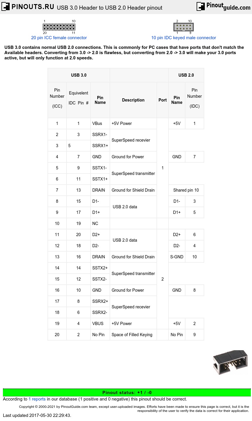
USB 3.0 Header is a 20 pin 2mm pitch header using the less common ICC pin numbering. The header has a key slot on the pin 1-10 side if enclosed.
USB 2.0 Header is a 10 pin .1 pitch header using the standard IDC pin numbering. The header has a key slot on the pin 1-9 side if enclosed. (The 10-pin IDC male graphic shown has the keying on the wrong side).
Both headers contain two ports each, and have a missing pin for filled female connectors.
The standard USB 2.0 Header is missing pin 9 (for keying), but logically pin 9 is for port1's Sheild GND. The sheild is left unconnected if a single port cable is plugged in to port 1. Dual Port hear connectors, share port 10 for both sheilds
This is the most common USB 2.0 header (10 pin [2x5], missing pin 9) and it is pin compatable with the rare 8 pin [2x4] version (missing pins 9 and 10) and 10 pin [2x5] (no pins missing). It is not pin compatable with the very rare (10 pin [2x5], missing pins 10 and 2).
A new feature of USB 3.0 is the SuperSpeed bus, which provides a fourth transfer mode at 5.0 Gbit/s, this is simply left out of the 2.0 header.

- USB 3.0 connector pinout
Time in Elektrostal , Moscow Oblast, Russia now
- Tokyo 05:57PM
- Beijing 04:57PM
- Kyiv 11:57AM
- Paris 10:57AM
- London 09:57AM
- New York 04:57AM
- Los Angeles 01:57AM
Time zone info for Elektrostal
- The time in Elektrostal is 8 hours ahead of the time in New York when New York is on standard time, and 7 hours ahead of the time in New York when New York is on daylight saving time.
- Elektrostal does not change between summer time and winter time.
- The IANA time zone identifier for Elektrostal is Europe/Moscow.
Time difference from Elektrostal
Sunrise, sunset, day length and solar time for elektrostal.
- Sunrise: 03:43AM
- Sunset: 09:07PM
- Day length: 17h 24m
- Solar noon: 12:25PM
- The current local time in Elektrostal is 25 minutes ahead of apparent solar time.
Elektrostal on the map
- Location: Moscow Oblast, Russia
- Latitude: 55.79. Longitude: 38.46
- Population: 144,000
Best restaurants in Elektrostal
- #1 Tolsty medved - Steakhouses food
- #2 Ermitazh - European and japanese food
- #3 Pechka - European and french food
Find best places to eat in Elektrostal
- Best pubs & bars in Elektrostal
- Best steak restaurants in Elektrostal
- Best bbqs in Elektrostal
The 50 largest cities in Russia
THE 10 BEST Things to Do in Elektrostal
Things to do in elektrostal.
- 5.0 of 5 bubbles
- 4.0 of 5 bubbles & up
- Good for a Rainy Day
- Good for Kids
- Good for Big Groups
- Adventurous
- Budget-friendly
- Hidden Gems
- Good for Couples
- Honeymoon spot
- Good for Adrenaline Seekers
- Things to do ranked using Tripadvisor data including reviews, ratings, photos, and popularity.

1. Electrostal History and Art Museum

2. Statue of Lenin

3. Park of Culture and Leisure
4. museum and exhibition center.

5. Museum of Labor Glory

7. Galereya Kino
8. viki cinema, 9. smokygrove.

10. Gandikap
11. papa lounge bar, 12. karaoke bar.

IMAGES
VIDEO
COMMENTS
USB 3.0 details. USB 3.0 is the third major version of the Universal Serial Bus (USB) standard for interfacing computers and electronic devices. USB 3.0 combines USB 2.0 bus and new SuperSpeed bus with transfer rate up to 5.0 Gbit/s, which is about ten times faster than the USB 2.0 standard. USB 3.0 connectors are usually distinguished from ...
2.1 Signal Descriptions and Pin Assignments For the purpose of discussion, it is assumed that the front-panel implementation involves a daughter card. The USB 3.0 internal cable connector A, or USB3 ICC A, is mounted on the motherboard, while the USB 3.0 internal cable connector B, or USB3 ICC B, is mounted on the daughter card.
USB type A and type B pinout (male and female) USB Type-A is used to make a connection with a PC while Type B is used to connect smaller peripherals. In other words, Type A is a downstream connector, while Type B is an upstream connector. The USB type A is rectangular, while type B has a square-like shape. Both of them have 4 pins.
USB 3.0 connectors are usually distinguished from their USB 2.0 counterparts by blue color-coding of the receptacles and plugs. USB 3.1 is the successor standard (USB 3.1 Gen 2), was released in July 2013 with the new transfer mode SuperSpeed+ that can transfer data at up to 10 Gbit/s (1.25 GB/s, twice the rate of USB 3.0). Communication is ...
They are: Regular, Mini and Micro. The connectors are also different based on the version of the USB i.e., USB 1.1 and USN 2.0 have a similar connectors and ports but when it comes to USB3.0, they are completely different. USB Type C sorted this whole mess with a single connector. Before looking at the USB pinout of different USB ports, here is ...
3.2 Cable Construction and Wire Assignment . 3.2.1: Cable Construction . Figure 3-2 illustrates a USB 3.0 cable cross-section. There are three groups of wires: UTP signal pair, Shielded Differential Pair (SDP, twisted or twinax signal pairs), and power and ground wires. The UTP is intended to transmit the USB 2.0 signalling while the SDPs are ...
The USB-PD protocol allows the host and device to negotiate power, delivering up to 100W across the USB cable. This is a big boost over USB 1.0 and 2.0's 2.5W and USB 3.0's 7.5W. The USB-PD charges several devices simultaneously, laptops, and other high-powered devices faster. USB-PD lets devices negotiate power for optimal charging.
This connector mainly works for peripherals like printers and scanners. Pinout. Like the Type-A USB, the older versions of Type-B have four pins, while the newer 3.0 versions have nine pins. Here's a table showing all the pins: Also, there is a second type of Type-B connector that has two extra pins: 10. DPWR.
Like USB 3.0, USB 3.1 uses one legacy USB 2.0 differential pair, and two SuperSpeed differential pairs (for a total of 6 pins), plus pins for power and ground. Wikipedia has the pinout details. USB C for USB 3.0/3.1 was made to work no matter which way you plug it in, so it uses roughly half the available pins, plus two pins to select which ...
2.1 Signal Descriptions and Pin Assignments […] Figure 2-1 illustrates the USB3 ICC pin numbering. Note that the connector include[s] two USB ports. ... The 20 pin usb 3.0 connector socket passively allows two usb 3.0 female type A sockets two be wired in...
The 24-pin double-sided connector offers a USB-C port that measures 8.4 x 2.6 x 6.65 mm. The 8.4 millimeters (~0.33 inches) is its width, the 2.6 millimeters (~0.10 inches) is its height, and the depth of 6.65 millimeters (~0.262 inches). The dimensions are for the internal side of a receptacle and outer side of a plug.
USB Type B Pinout. The Type B connector has four pins in its older generations and nine pins in standard 3.0: Looking at the Type B connector on a cable, the pins are numbered 1-4, ascending, clockwise from top left in the central rectangular portion of all generations. The third generation adds a row of pins above, numbered 9-5 descending from ...
Pin 10 is detect the front USB 3.0 cable. The cable IO before this PIN, so that the system knows that the cable is installed. ... This work around is not recommended or supported, as it suggests the system cable is installed, and of course before USB 3.0 ports will not work. As an employee of HP, I must say this. ;-) ...
Structure of USB A Pinout. The USB A pinout consists of four pins, each with a unique function: VCC (Pin 1): This is the power supply pin, providing a +5V voltage to the connected device. D- (Pin 2): This is the Data Minus pin, responsible for carrying data. D+ (Pin 3): This is the Data Plus pin, working together with Pin 2 for data transmission.
The USB Type-C plug. Image courtesy of Microchip. USB 2.0 Differential Pairs. The D+ and D- pins are the differential pairs used for the USB 2.0 connectivity. There are two D+ pins and two D- pins in the receptacle. However, the pins are connected to each other and there's actually only one USB 2.0 data differential pair available for use.
In 1938, it was granted town status. [citation needed]Administrative and municipal status. Within the framework of administrative divisions, it is incorporated as Elektrostal City Under Oblast Jurisdiction—an administrative unit with the status equal to that of the districts. As a municipal division, Elektrostal City Under Oblast Jurisdiction is incorporated as Elektrostal Urban Okrug.
Converting from 3.0 -> 2.0 is flawless, but converting from 2.0 -> 3.0 will make your 3.0 ports active, but will only function at 2.0 speeds. USB 3.0 Header is a 20 pin 2mm pitch header using the less common ICC pin numbering. The header has a key slot on the pin 1-10 side if enclosed.
Permission is granted to copy, distribute and/or modify this document under the terms of the GNU Free Documentation License, Version 1.2 or any later version published by the Free Software Foundation; with no Invariant Sections, no Front-Cover Texts, and no Back-Cover Texts.A copy of the license is included in the section entitled GNU Free Documentation License.
Sunset: 09:07PM. Day length: 17h 24m. Solar noon: 12:25PM. The current local time in Elektrostal is 25 minutes ahead of apparent solar time.
9. SmokyGrove. 10. Gandikap. 11. Papa Lounge Bar. 12. Karaoke Bar. Top Things to Do in Elektrostal, Russia: See Tripadvisor's 801 traveller reviews and photos of Elektrostal tourist attractions.